
On CNC machine tools, not only the precise speed control of the spindle is required, the low-frequency torque is large, and the response is fast, but also the precise positioning control of the spindle is required.
I. Overview
On CNC machine tools, not only the precise speed control of the spindle is required, the low-frequency torque is large, and the response is fast, but also the precise positioning control of the spindle is required. 6730V adds positioning and carry functions on the basis of high-performance closed-loop vector control, which can realize arbitrary point positioning and arbitrary angle carry on the spindle.

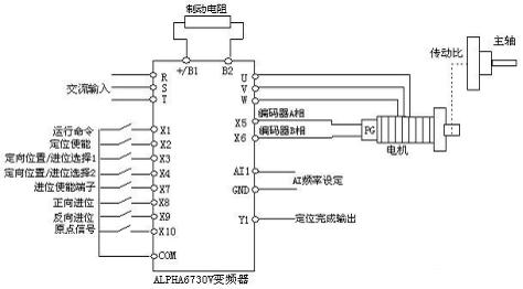
figure 1
Second, the hardware connection
Figure 1 shows the hardware connection of 5.5KW inverter. The running command is given by the terminal, and the frequency setting is given by analog AI1. The motor uses an incremental encoder, AB is connected to the X5 and X6 terminals, and the transmission ratio P6.08 between the motor and the spindle is set. If the encoder is installed on the spindle, you need to set P2.49, P2.50 and P6.08 to 1.
3. Commissioning instructions
1. Closed loop vector. Because the system operates under closed-loop vector control, first ensure that the closed-loop vector operates normally. Firstly, auto-tuning the motor parameters, disconnecting the motor from the load, PA.29=2 (rotation tuning). If it cannot be disconnected from the load, PA.29=1 (static setting). Or directly copy the parameters of the same type of motor. Set the encoder line number P2.44. P0.01=1 (closed loop vector control). First, digitally set P0.02=10HZ, run, if you run at a lower frequency and the current is large, you should change the encoder AB phase to a phase sequence.
2. Positioning function. The positioning function is set when P6.07=1 when the closed-loop vector can run normally, and the positioning function module is valid. The position of the main shaft is determined by the number of pulses, and any position can be used as a reference of 0°, and the main shaft rotates 360° correspondingly: encoder pulse number*transmission ratio*4. For example, if the encoder is 1000 lines and the transmission ratio is 1.5, 360° corresponds to: 1000*1.5*4=6000 pulses. If you want to stop at 60°, the setting value of P6.11 is: 60/360*(1000*1.5*4 )=1000. When the reference 0° is determined, the spindle can be stopped at a certain angle, and then the pulse value corresponding to the angle is calculated according to the above formula, and the current position display (P6.46) can be adjusted to this pulse value. Four positioning angles (P6.11~6.14) can be set, which can be selected by selecting terminals. If more positioning angles are needed, they can be set through communication. Set PC.21=1, you can view the current position of the spindle in the monitoring state.
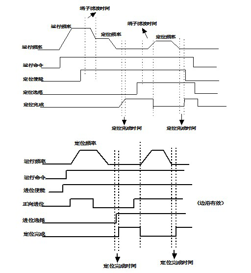
In addition, after the positioning is completed, carry processing can be carried out, or before the given running command, if the carry enable is valid, the positioning completion is output directly, and the carry command can be received. The positioning enable command is invalid when the carry is enabled. The carry angle is also set in a pulse manner, and the calculation method is the same as above. The timing is shown in Figure 2.

figure 2
4. Summary
During positioning, the inverter first runs to the positioning frequency and then executes the positioning process. If overshoot occurs, the positioning frequency can be reduced appropriately, or the positioning time can be extended or the proportional gain can be reduced. The goal is to minimize positioning time without overshoot. After on-site debugging, 6730V can fully meet the positioning accuracy requirements, and can completely replace the servo in the spindle positioning occasion to save a lot of CNC machine tool costs.