
Hydraulic presses, also known as hydroforming presses, are machines that use Pascal's law to make use of liquid pressure transmission, and are used to shape and process various metallic and non-metallic materials.
I. Overview
Hydraulic presses, also known as hydroforming presses, are machines that use Pascal's law to make use of liquid pressure transmission, and are used to shape and process various metallic and non-metallic materials. It has a wide range of applications and is suitable for stamping processes such as bending, flanging, stretching, forming, and cold extrusion. The press is a product that is processed by static pressing. It is suitable for the compression molding process of metal powder products and non-metallic materials, such as plastics, glass fiber reinforced plastics, insulating materials and abrasive products. It can also be used for calibration and press-fitting processes. Since its advent in the 19th century, it has developed rapidly. The wide adaptability of hydraulic presses in work has made it widely used in various sectors of the national economy.
2. Working principle
The hydraulic press mainly includes a frame, a hydraulic system, a cooling system, a pressurized oil cylinder, an upper mold and a lower mold. The pressurized oil cylinder is installed at the upper end of the frame and is connected with the upper mold, and the cooling system is connected with the upper mold and the lower mold. The utility model is characterized in that the lower end of the rack is equipped with a mobile worktable and a mobile oil cylinder connected with the mobile worktable, and the lower mold is placed on the mobile worktable.
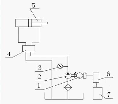
As an important part of the entire machinery, the hydraulic system directly affects the performance of the entire press.It is mainly composed of the following parts:
1) Hydraulic pumps for energy devices. It converts the mechanical energy output by the power part (electric motor or other remote engine) into hydraulic energy to provide pressure oil to the system.
2) One-to-one hydraulic machine (hydraulic cylinder, hydraulic motor). By converting hydraulic energy into mechanical energy, the load is driven to do work.
3) Control device one by one hydraulic valve. Through their control and adjustment, the pressure, flow rate and direction of the liquid flow can be changed, thereby changing the force (or torque), speed and direction of the actuator. According to different control functions, hydraulic valves can be divided into village force control valves, Flow control valve and directional control valve. Pressure control valves are divided into benefit valves (safety valves), pressure reducing valves, sequence valves, pressure relays, etc.; flow control valves include throttle valves, regulating valves, diverting and collecting valves, etc.; directional control valves include check valves, Hydraulic control check valve, shuttle valve, directional valve, etc. According to different control methods, hydraulic valves can be divided into on-off control valves, fixed value control valves and proportional control valves.
4) Auxiliary devices: oil tanks, pipelines, accumulators, oil filters, pipe joints, pressure gauge switches, etc., through these components to connect the system to achieve various working cycles.
5) Working medium hydraulic oil. Most hydraulic oils use mineral oil, and the system uses it to transfer energy.
Disadvantages of current hydraulic presses:
The power in the hydraulic transmission system is provided by the oil pump driven by the motor. During the plasticizing cycle of the workpiece,
u The hydraulic machine needs different flow and pressure under different processes, and must rely on proportional flow valves and pressure valves to adjust the flow and pressure required for different processes
u As the quantitative pump cannot adjust the output power, the excess energy can only be consumed in the baffle, oil leakage, oil temperature rise, aggravating the wear of various valves, and causing the oil temperature to be too high and the motor noise to be too loud , And shortened mechanical life.
u And the capacity of the designed motor is usually much higher than the actual need, there is a phenomenon of "large horse-drawn cart", which results in a waste of energy.
Therefore, popularizing the application of frequency converters on hydraulic presses is of great significance for reducing energy costs. More importantly, the digital servo control of the hydraulic machine can be achieved through frequency conversion control
3. System configuration
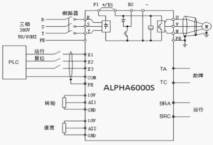
In view of the above shortcomings of the press, we proposed a frequency conversion transformation plan and adopted the following methods for transformation:


Use PLC to replace the time relay in the original electrical system, and the intermediate relay realizes the control logic of the entire hydraulic press, and controls the operation of the frequency converter to stop. The fault output signal of the inverter is fed back to the PLC input terminal. When the inverter fails, the PLC stops working and outputs a fault indication to notify the operator. Adjust the speed potentiometer to adjust the working speed of the oil cylinder; adjust the torque potentiometer to adjust the maximum output torque of the inverter, thereby controlling the maximum working pressure of the oil cylinder.
Four, system advantages
1. Due to the removal of relief valves, throttle valves, etc., the whole system is more concise and the points of failure are reduced.
2. It is more convenient to adjust the pressure and flow rate; if the recipe function of the host computer is used together, it can fully realize the automation of different processing requirements.
3. The oil pump is set to operate according to the process requirements. There is no longer any excess oil flow back to the mailbox through the overflow valve, which reduces the oil temperature and prolongs the use time of the oil.
4. During the replacement of the workpiece gap, the motor is in a stopped state, saving electricity.