
At present, among the oil field pumping equipment, the beam beam pumping unit is the most common application and the largest number.
I. Overview
At present, among the oil field pumping equipment, the beam beam pumping unit is the most common application and the largest number. However, the traditional kowtow machine generally has many problems such as large starting shock, high power consumption, large horse-drawn carriages, low efficiency, etc. In addition, the situation of the oil well is complicated, the phenomenon of heavy oil, wax formation, and shaka is more, and the rod is broken and burned. Motors and other phenomena often occur, there is no reliable protection function for the motor, and the amount of equipment maintenance is large. Therefore, it is urgent to modify the existing pumping unit equipment.
The frequency converter has a low-speed soft start, the speed can be smoothly adjusted in a large range, and it has complete protection functions for the motor, such as short circuit, overload, overvoltage, undervoltage and stall, etc., which can effectively protect the motor and mechanical equipment. Reliability, improved efficiency and many other advantages are ideal solutions for the transformation of pumping equipment, and its application effect is very obvious.
2. Working principle
1 As an oil pumping device, its movement is to lift up and down repeatedly, one stroke at a time, and its power comes from two heavy steel sliders driven by the motor. When the slider is lifted, it acts like a lever. The sucker rod is sent into the well. When the slider is lowered, the sucker rod is raised to bring oil to the wellhead.
2 Due to the constant speed of the motor, the load is reduced during the descent of the slider, and the energy generated by the motor dragging is nowhere to be released, and it will inevitably enter the state of regenerative power generation, causing the main circuit bus voltage to increase, and frequent high-voltage shocks will damage the main inverter. Devices, including electrolytic capacitors and power modules, therefore increase the braking circuit, so that the regenerative voltage can be released in time to ensure that the equipment operates at a safe voltage.
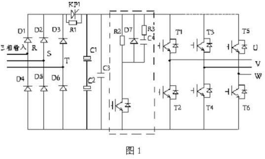
3 The regenerative braking circuit is the so-called brake circuit, as shown in the dotted frame in Figure 1, including the comparison circuit, brake module and brake resistor. The control block diagram is as follows:

We amplify the sample from the main circuit, compare it with the reference voltage, and adjust the potentiometer to make the brake unit conduct at 1.1Ue (Ue is the rated bus voltage value), and disconnect at 1.05 Ue to control the main circuit. Voltage, to ensure that it works within the allowable range.
4 Because the brake module controls the voltage of the main loop with a single junction, its reliable operation is critical,
Here, the absorption circuit needs to be completed. Because the brake resistance leads are relatively long, the lead inductance and peak voltage are correspondingly increased. For this purpose, R, C, and D absorption circuits are used. R3 and C4 are used to absorb the lead inductance. Peak voltage, the added fast recovery diode is used to provide a path for the reverse voltage generated across the brake resistor when the brake unit is turned off. When the brake unit works frequently, it will inevitably produce interference voltage, which will cause the module to be undesirably turned on and damaged. It is necessary to add an anti-interference capacitor to the signal input terminal to absorb the module due to the interference signal. Generally, a non-inductive capacitor of about 0.01uF is suitable.
5 The current limit of the braking unit is generally not large due to the current limitation of the braking resistor. It is sufficient to select about 100A. Since the braking resistor works once in each stroke, its power should be sufficient to ensure long-term reliable use. Generally, 10Kw/80Ω Electric stove wire.
6 ALPHA inverter main circuit schematic diagram
The power device of ALPHA frequency converter is Siemens IGBT, the core of the controller is Hitachi H8 single-chip microcomputer, the quality is stable and reliable.
The ALPHA frequency converters we apply are all AC-DC-AC voltage source type inverters, and their circuits are shown in Figure 1:

3. System configuration
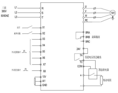
Pumping unit wiring diagram:

4. Revenue from transformation
We selected the pre-wells and the mid-to-late wells to carry out the transformation feasibility analysis and have successfully applied them to multiple applications
Use the scene.
1 In the early wells, due to the new mining, the oil storage is large, and the liquid supply is sufficient.
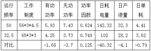
In the high-speed mode, the frequency converter is operated to 65Hz, the frequency is increased by 1/3, the motor speed is increased by 30%, and the oil recovery is also increased. The comprehensive oil recovery rate can be 20% more oil than the power frequency. It has increased by 1.2 times and is very popular with oilfield oil producers.
2 In the middle and late wells, due to reduced well reserves and insufficient fluid supply, if the motor is still running at power frequency, it will inevitably waste electrical energy and cause unnecessary losses. Therefore, we use the method of reducing the speed to reduce the stroke, generally the frequency of the inverter Operating between 35 and 40 Hz, the motor speed is reduced by 30%, and the general load of oil extraction equipment is lighter, its power saving rate can reach about 25%, and the power factor is improved and the reactive power loss is reduced.
3 The frequency converter also has a soft start/soft stop function. When the motor is started, the mechanical impact on the sucker rod is reduced, and the heavy oil, wax, sand, etc. can be effectively protected and stopped to protect the motor and Mechanical equipment can reduce maintenance and prevent broken rods. The inverter can reliably protect against overvoltage, undervoltage, overload, short circuit and motor stall, and it has a good effect on extending the life of the motor and reducing the wear of mechanical equipment. effect.
In summary:
The application of frequency conversion speed governor in the pumping unit can improve the work efficiency, increase the oil production, save the electric energy and protect the motor and equipment. Its application prospect is very broad. There are quite a lot of oil pumping equipment in our country. I believe that the frequency converter can do a lot in this respect.
The following picture is the actual picture of the application of the special inverter of Alpha pumping unit in Shengli Oilfield:


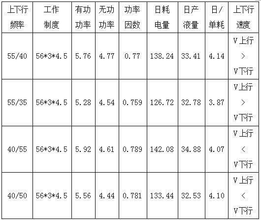
2 Set different up and down stroke speeds for the same stroke to run the pumping well:
Make sure that the original stroke frequency is still 4.5 times. Set different up and down frequencies and change the up and down speeds to adapt to the well conditions of a single well. Measure the relevant data during operation.

3 Actual use and measurement data comparison results:
a Through the comparison of measurement data, the inverter can ensure the optimization trend of increasing the daily liquid production and decreasing the daily power consumption under the condition of willing operation parameters. The minimum daily power consumption is 126.72KWh, the power saving rate is 10.96%, and the unit consumption of liquid production is reduced by more than 0.4, which meets the requirements of oil production technology and energy saving.
b The instrument has other features in operation and use:
① Zero-start and soft-start functions reduce the impact of pumping well start-up on the power grid, extend the service life of the motor, and reduce equipment maintenance costs.
② To meet the requirements of the oil production process, the stroke number and the up and down stroke speed can be arbitrarily set to reduce the pump leakage coefficient during the lifting process and make the pumping well run in the best state.
③ The operation interface is simple and intuitive, with key interlock function to prevent staff from misoperation, complete protection function, and alarm function.