
I. Overview
Yuxi Xinxing Iron and Steel Co., Ltd. is a steel conglomerate that Kunshan Iron and Steel Group has implemented in the province’s multiplication plan and made full use of the resource advantages of Yuxi to expand in Hongta District. The company was completed and put into production on March 15, 2005. The main products are: rectangular continuous casting billet, slab, hot-rolled ribbed steel bar, medium and wide band, etc. The products sell well in Yunnan, Sichuan, Chongqing, Guangdong and other markets. Under the excellent situation of continuous improvement of the market economy system, acceleration of reform and opening up, and development of the western region, Yugang seizes opportunities to accelerate development, widely absorbs the successful experience of domestic and foreign excellent steel companies, optimizes the process structure, and vigorously promotes technological progress and energy conservation The work of reducing consumption and cleaner production has made the structure of steel products more reasonable, and the market competitiveness has been significantly enhanced. A qualitative leap has been achieved in the modernization, intensive and efficient industrial process. Energy conservation and environmental protection and economic development have made greater contributions.
2. Working principle
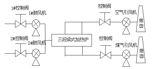
The medium and wide-band operation area adopts a three-section beam heating furnace. The air supply volume is adjusted by the air inlet valve. The blower is designed for one use and one standby. It operates 24 hours.
In normal production, when the heating cold steel is damaged, the blower inlet valve opening is 70~80%, and the supply air pressure is maintained at about 4.5kPa to ensure the furnace heating temperature.
When the heating hot steel is damaged, the blower inlet valve opening is 50~60%, and the supply air pressure is maintained at about 4.5kPa. When the heating furnace is insulated, the supply air demand is less, and the inlet valve opening is reduced accordingly. The wind pressure is kept at about 4.2kPa.
Gas exhaust and air exhaust air volume are regulated by air inlet valve. In normal production, when the heating cold steel is damaged, the gas exhaust fan air exhaust inlet valve opening is 70-85%. In normal production, the heating steel is damaged, the gas exhaust fan air exhaust fan inlet valve opening is 50~60%, when the heating furnace keeps heat, the opening of the inlet valve of the two fans is 30%.
The air inlet valve of the air exhaust fan is adjusted according to the steel rolling speed to ensure the uniform temperature in the furnace. The exhaust temperature of the two is controlled within 100 ℃, and the alarm is over 180 ℃. The heating furnace fan process is simple The picture is as follows:

3. System configuration
The three-section beam heating furnace blower, gas induced draft fan, and air induced draft fan, because the selection of the motor and fan is based on the maximum production capacity of the heating furnace, because the actual production capacity has not reached the maximum production capacity, the adjustment gate, The method of increasing the fluid resistance of the pipe network to achieve the flow control, so the system has low efficiency, large power consumption, and serious waste of electrical energy.
Due to the continuous and stable air supply required during normal production, the air volume and air pressure do not change much. At this time, the throttling loss can be eliminated by the adjustment of the fan speed by the frequency converter, and at the same time, the operating efficiency of the fan can be improved, although due to the load rate of the motor The drop will reduce its operating efficiency, but due to the large decrease in the operating power of the fan, the loss of the motor is also reduced, and ultimately the operating power of the motor is greatly reduced, thereby achieving the purpose of saving electricity.
1 Variable speed principle:
According to the basic principles of electromechanics, the speed principle of the motor satisfies the following relationship:
n=(1-s)60f/p
In the formula: P-motor pole pair number
F-motor operating frequency
S-slip
It can be seen from the formula that the synchronous speed N1 of the motor is proportional to the operating frequency N of the motor. Since the slip S is generally smaller than 0.05, the actual speed N of the motor is approximately equal to the synchronous speed N1 of the motor, so the power supply of the motor is adjusted Frequency F can change the actual speed of the motor.
And changing the frequency must change the supply voltage, the electromagnetic relationship produced by the AC motor:
E=4.44fwØ
In the formula: E-motor electromotive force
f-stator frequency
w-winding coefficient
Ø-Air gap main flux
When adjusting the speed of different frequency motors, we hope that the main magnetic flux Ø is constant, and the u/f curve is kept constant. Therefore, when the frequency is changed, the power supply voltage also changes.
2 Principle of power saving by fan speed regulation:
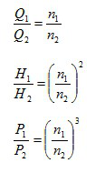
Due to the complexity of the fluid inside the fan, theory alone cannot accurately calculate their performance. The operating conditions of the fan can only be calculated by means of experiments and simulations by relying on similar theories in fluid mechanics. When the similar law is applied to the same fan running at different speeds, the following formula can be obtained:
When changing the speed of the fan, the relationship between its speed n, flow Q, pressure (head) H, and shaft power P is:

As can be seen from the above formula, the flow rate is proportional to the speed, the pressure is proportional to the square of the speed, and the shaft power is proportional to the cube of the speed, so reducing the speed can greatly reduce power consumption. The power saving principle of the fan is to replace the damper with a speed regulating device to adjust the flow, reduce the loss of energy saving and save electricity. The fan is a mechanical device used to transmit gas. The fan is a machine that converts the shaft power of the motor into mechanical energy. Their starting torque is small, the load is light, and they have great energy saving potential.
3 Transformation plan:
The current control method of the heating furnace blower is mainly based on the requirement of the combustion furnace's combustion air volume. The air induced fan and gas induced fan are mainly achieved by adjusting the valve opening according to the induced air temperature and the furnace chamber temperature. Due to the relatively simple process of combustion-supporting blower and induced draft fan, there is no need to do closed-loop control. The transformation plan considers keeping the air inlet valve fully open after using the frequency converter, and manually adjusting the fan speed according to production needs. The system can change the amount of induced wind at any time to adapt to the changes, maintain the normal economic operation of the fan, and achieve the purpose of stable control, convenient operation, and energy saving.
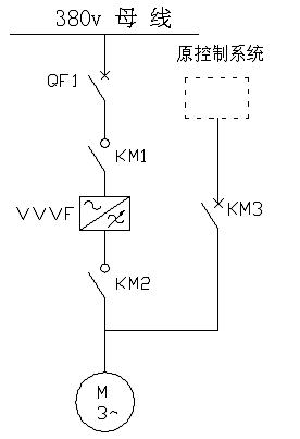
In addition, in order to ensure the reliability of the system, the existing control equipment and operation mode of the blower fan will remain. The control circuit is designed with power frequency/frequency conversion switching options. The power/frequency selection is manually switched to achieve combustion-supporting centrifugal fans. Power frequency or frequency conversion operation. Because the heating furnace blower is one-use and one-standby, the frequency conversion transformation adopts one-to-two frequency conversion control mode, and the manual switching function of 1# and 2# fans is set.

Main circuit diagram
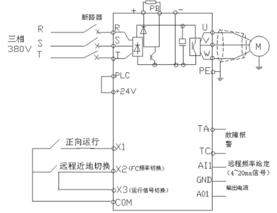
In order to reduce the labor intensity of the on-duty workers, after the transformation, the start/stop, combustion/transition switching, and speed control of the combustion air blower and induced draft fan are both centralized and remote. The existing PLC computer control system is used, and the existing PLC is used. The standby point of the module increases the speed control operation function of the blower and the induced draft fan and the display function of the output frequency and output current of the inverter by modifying the program in the fuel control computer control system.

4接线图:4 Wiring diagram:

4. Revenue from transformation
After the transformation, the operating parameters of the gas induced draft fan motor are:

According to the actual use results above:
The average power saving rate is more than 40%, and the cost can be recovered in about a year.